MAXIMUM SHEAR STRESS
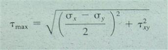
On a different orientation of the stress element, the maximum shear stress will occur. Its magnitude can be computed from
Eq. 4-4. Maximum shear stress
FIGURE 4-5
Maximum shear stress element
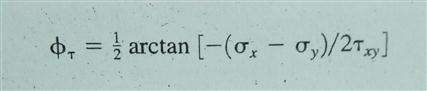
The angle of inclination of the element on which the maximum shear stress occurs is computed as follows:
Eq. 4-5. Angle for Maximum
Shear Stress Element
The angle between the principal stress element and the maximum shear stress element is always 45°.
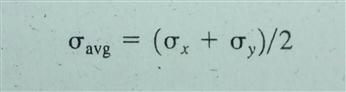
On the maximum shear stress element, there will be normal stresses of equal magnitude acting perpendicular to the planes on which the maximum shear stresses are acting. These normal stresses have the value
Eq. 4-6. Average Normal Stress
Note that this is the average of the two applied normal stresses. The resulting maximum shear stress element is shown in Figure 4-5. Note, as stated above, that the angle between the principal stress element and the maximum shear stress element is always 45°.
Summary and General Procedure for Analyzing Combined Stresses
The following list gives a summary of the techniques presented in this section; it also outlines the general procedure for applying the techniques to a given stress analysis problem.
1. Decide for which point you want to compute the stresses.
2. Clearly specify the coordinate system for the object, the free-body diagram, and the magnitude and direction of forces.
3. Compute the stresses on the selected point due to the applied forces, and show the stresses acting on a stress element at the
desired point with careful attention to directions. Figure 4-3 is a model for how to show these stresses.
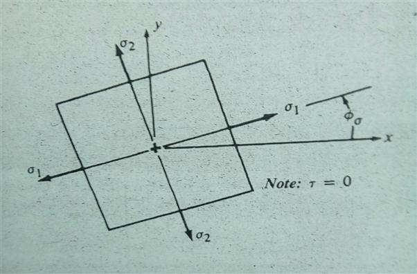
4. Compute the principal stresses on the point and the directions in which they act. Use Equations 4-1, 4-2, and 4-3.
5. Draw the stress element on which the principle stresses act, and show its orientation relative to the original x-axis. It is recommended that the principal stress element be drawn beside the original stress element to illustrate the relationship between them.
6. Compute the maximum shear stress element and the orientation of the plane on which it acts. also, compute the normal stress that acts on the maximum shear stress element. Use Equations (4-4), (4-5), and (4-6).
7. Draw the stress element on which the maximum shear stress acts, and show its orientation to the original x-axis. It is recommended that the maximum shear stress element be drawn beside the maximum principal shear stress element to illustrate the relationship between them.
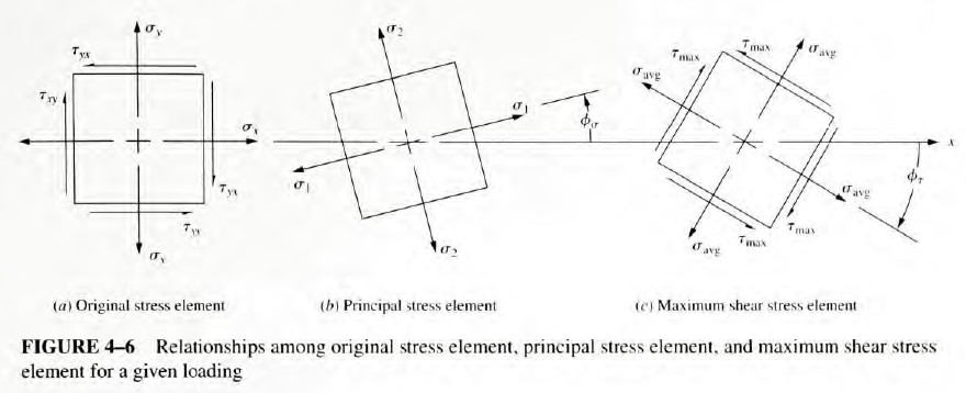
8. The resulting set of three stress elements will appear as shown in Figure 4-6.